Regular Expressions in Construction

Regular expression is quite underestimated technology in Construction and Engineering world. Mostly cause its looks quite weird, not intuitive, and complicated. But that’s only looks. This article shows how to use it without issues. To do so we limit syntax by few most useful symbols – dot and astricks, and wrap it into brackets. Its easiest way to read, understand and implement for your tasks.

Use regular expression with BIM - regex example with Tag and Token

In engineering world searching mostly based on project naming conventions. With regex you can identify that equipment is match with conventions. Check items that do not match with it at all. Setup income data check. Implement rapid fixes.

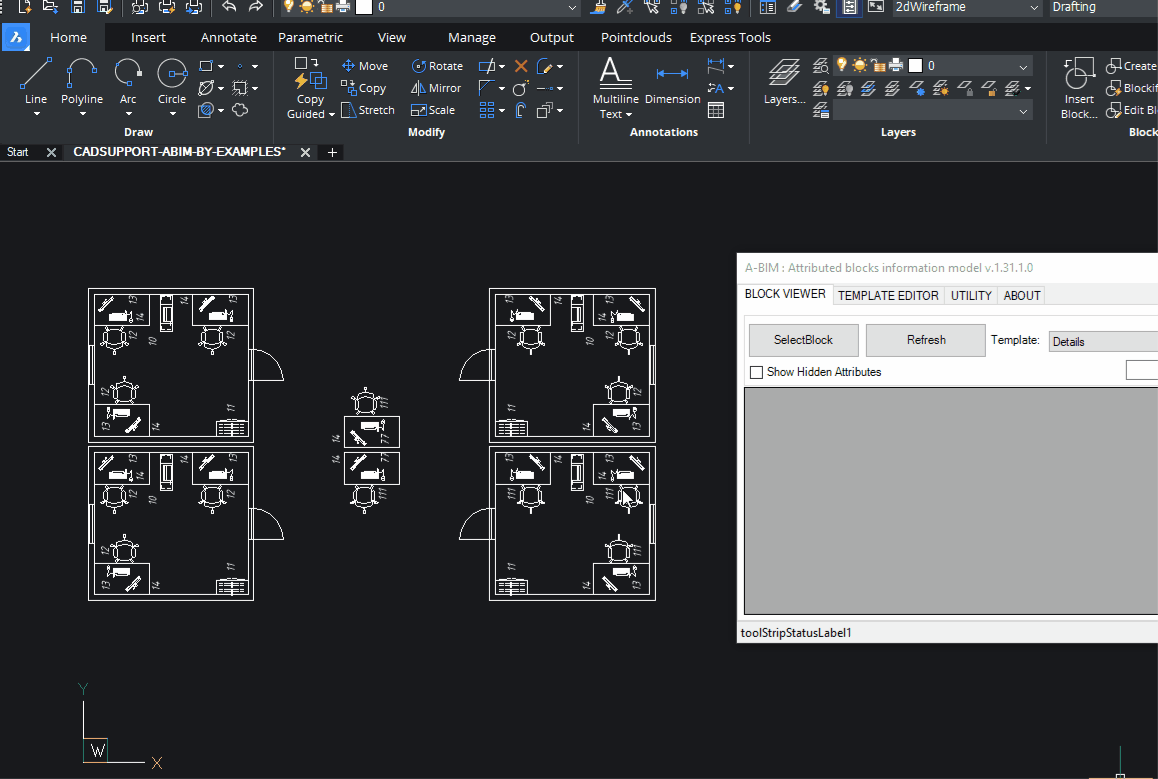
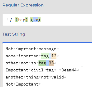
Regex – its a kind of pattern language. You define pattern value, and engine use it to find anything that much with it. What make it powerful – is Tokens. Your search patten can contains more than one item to search simultaniously, and as soon as it has been found – you can play with that.

Continue reading

BIM in Blender with Bonsai

Liberation of 3D grapfic with tools such as Blender – always had the potential to change the ground not only for visual part, but also potential to unlock all sort of other implementations –  SOLID, CAD, BIM.

Blender already took a huge share on additive technology market, by replacing usual CAD and SOLID tools for engineering. Many cases shows that mesh modeling in fact gives shortcut from idea to product printout.

But now It goes to new and literaly big area – BIM software free by nature, with unlimited customization potential for all sort of implementation. It might overthrow current balance in Construction industry:

Blender Bonsai Bim Ifc

BonsaiBIM extension for Blender blends CAD modeling with 3D enviroment with align of BIM approach and IFC specifications.

NavisWorks – SearchSet’s

With NavisWorks Simulate and Manage you can use Find Items panel to search across details. Usual flow – is to identify Category and properites which allow to find right element. Then design the query. If query is correct – you can proceed with result, if not you can adjust query. When you query is perfect, and for some reason you may need it again – sets are desinged to help you.

When you get collection of search sets – it might be userfull to export it and use same set with another NavisWorks models. So lets dive deeper it this matter.

NavisWorks Search Sets

Continue reading

3D model at construction site

How was the 3D model created?

For industrial area common practice is to make an EPCI tender. Where E – means Engineering, which includes FEED study.

Rough 3D model appears at FEED study to help briefly estimate expenses, clarify technical details, define approximate facility layout.

When Final Investment Decision is made – Engineering start to model facility with all details.
Basically, 3D model is a product of engineering processes, as well as drawings, take off quantities, and specifications.

Industrial area 3D model for construction activities

Who uses 3D model in Construction?

Continue reading

NavisWorks C# Api Sections

NavisWorks C# API Section Tools enable sectioning via c# .Net and COM

Often its’ important to have some code snippets to be able to solve concreate task in NavisWorks via .NET API at C# language. Cause documentations is not always self explanatory. Especially in case COM API. So for Cutting and Section planes in navis samples Bello is able to do the job.

CONTENT

By Xiaodong Liang

Origin was available here: http://adndevblog.typepad.com/aec/2012/08/create-sectioning-plane.html

Currently, only COM exposed some small API for sectioning. InwClippingPlaneColl can add the custom clipping plane. But InwClippingPlaneColl.Add method is not supported. This is because the COM wrapper in having to follow the underlying C++ code.
You need to use InwClippingPlaneColl2.CreatePlane. It passes in a 1 based index. Default planes will be created as required, up to and including this index. Then you modify the plane that is in the collection directly.

        private void createSectionPlane()
        {
            ComApi.InwOpState10 state;
            state = ComBridge.State;

            // create a geometry vector as the normal of section plane
            ComApi.InwLUnitVec3f sectionPlaneNormal =
                (ComApi.InwLUnitVec3f)state.ObjectFactory(
                Autodesk.Navisworks.Api.Interop.ComApi.nwEObjectType.eObjectType_nwLUnitVec3f,
                null,
                null);
            sectionPlaneNormal.SetValue(1, 1, 0);

            // create a geometry plane
            ComApi.InwLPlane3f sectionPlane =
                (ComApi.InwLPlane3f)state.ObjectFactory
                (Autodesk.Navisworks.Api.Interop.ComApi.nwEObjectType.eObjectType_nwLPlane3f,
                null,
                null);

            //get collection of sectioning planes
            ComApi.InwClippingPlaneColl2 clipColl =
                (ComApi.InwClippingPlaneColl2)state.CurrentView.ClippingPlanes();

            // get the count of current sectioning planes
            int planeCount = clipColl.Count + 1;

            // create a new sectioning plane
            // it forces creation of planes up to this index.
            clipColl.CreatePlane(planeCount);

            // get the last sectioning plane which are what we created
            ComApi.InwOaClipPlane cliPlane =
                (ComApi.InwOaClipPlane)state.CurrentView.ClippingPlanes().Last();

            //assign the geometry vector with the plane
            sectionPlane.SetValue(sectionPlaneNormal, 1.0);

            // ask the sectioning plane uses the new geometry plane
            cliPlane.Plane = sectionPlane;

            // enable this sectioning plane
            cliPlane.Enabled = true;
        }

Create NavisWorks Section Box via .Net API

With .Net Api section box might be created as valid JSON object and assign to current View:

private void createSectionPlane(double centerX, double centerY, double CenterZ)
{                                

double halfSize = 5;
string clippingPlanesJson = 
           "{\"Type\": \"ClipPlaneSet\"," +
            "\"Version\":1,\"OrientedBox\":" +
           "{\"Type\":\"OrientedBox3D\"," +
            "\"Version\":1,\"Box\":" +
"[" +
    "[";
clippingPlanesJson += (centerX - halfSize).ToString() + ",";
clippingPlanesJson += (centerY - halfSize).ToString() + ",";
clippingPlanesJson += (centerZ - halfSize).ToString() + 
"],[" +
clippingPlanesJson += (centerX + halfSize).ToString() + ",";
clippingPlanesJson += (centerY + halfSize).ToString() + ",";
clippingPlanesJson += (centerZ + halfSize).ToString() + 
     "]" +
"],";
clippingPlanesJson += "\"Rotation\":[0,0,0]},\"Enabled\":true}";
                                Autodesk.Navisworks.Api.Application.ActiveDocument.ActiveView.SetClippingPlanes(clippingPlanesJson);

Add Sections Planes via Bridge COM

Add Sections Planes via Bridge COM

published att Autodesk Forum by bvgarbar

private void CreateSectionBox(Document doc, DocumentCurrentSelection selection)
{
var currentViewPoint = doc.CurrentViewpoint;
var viewPointValue = currentViewPoint?.Value;
var planes = viewPointValue?.InternalClipPlanes;
if (planes == null) return;

planes.SetMode(LcOaClipPlaneSetMode.eMODE_BOX);
if (planes.GetMode() != LcOaClipPlaneSetMode.eMODE_BOX) return;
BoundingBox3D box = selection.SelectedItems.BoundingBox();
//planes.FitToBox(box);
planes.SetBox(box);
planes.SetEnabled(true);
currentViewPoint.Value.ZoomBox(box);
}

How to create a Table and fill in its cells with .NET

originally this article was available at

https://adndevblog.typepad.com/autocad/2012/05/how-to-create-a-table-and-fill-in-its-cells-with-net.html

But now this source is not available anymore. So this is copy paste from web-archive for my own memory

05/16/2012

How to create a Table and fill in its cells with .NET

By Xiaodong Liang

The code below shows how to create a table and fill in its cells. Some obsolete methods of Table are still visible. You will receive a warning in compiling if using obsolete methods. Please use the newest methods.

[CommandMethod("testaddtable")]
public void testaddtable()
{
    Database  db =
        HostApplicationServices.WorkingDatabase;
 
    using (Transaction tr =
        db.TransactionManager.StartTransaction())
    {
        BlockTable bt =
            (BlockTable)tr.GetObject(db.BlockTableId,
                                    OpenMode.ForRead);
        ObjectId msId =
            bt[BlockTableRecord.ModelSpace];
        BlockTableRecord btr =
            (BlockTableRecord)tr.GetObject(msId,
                                OpenMode.ForWrite);
        // create a table
        Table tb = new Table();
        tb.TableStyle = db.Tablestyle;
        // row number
        Int32 RowsNum = 5;
        // column number
        Int32 ColumnsNum = 5;
        // row height
        double rowheight = 3;
        // column width
        double columnwidth = 20;

        // insert rows and columns
        tb.InsertRows(0, rowheight, RowsNum);
        tb.InsertColumns(0, columnwidth, ColumnsNum);
        tb.SetRowHeight(rowheight);
        tb.SetColumnWidth(columnwidth);

        Point3d eMax = db.Extmax;
        Point3d eMin = db.Extmin;
        double CenterY = (eMax.Y + eMin.Y) * 0.5;
        tb.Position = new Point3d(10, 10, 0);

        // fill in the cell one by one
        for (int i = 0; i < RowsNum; i++)
        {
            for (int j = 0; j < ColumnsNum; j++)
            {
                tb.Cells[i, j].TextHeight =  1;
                if (i == 0 && j == 0)
                    tb.Cells[i, j].TextString =
                        "The Title";
                else
                    tb.Cells[i, j].TextString =
                        i.ToString() + "," + j.ToString();
                tb.Cells[i,j].Alignment =
                    CellAlignment.MiddleCenter;
            }
        }

        tb.GenerateLayout();
        btr.AppendEntity(tb);
        tr.AddNewlyCreatedDBObject(tb, true);
        tr.Commit();
    }
}

ABIM (Attribute Block Information Model)

A design pattern for 2D/3D CAD engineering, where meaningful elements are created as blocks with defined attributes.

With this approach, each item in a drawing is not merely a collection of lines and circles—it becomes an object containing both graphical and meta information.

ABIM is intended to save time for engineers on projects that are either not significant enough or not specifically suited for full BIM modeling. This includes various types of diagrams and plans such as:

  • P&ID (Piping and Instrumentation Diagrams)
  • Small HVAC layouts
  • Piping, electrical, automation and technology plans and diagrams
  • Melioration and agricultural projects

These can be created in 2D or 3D, whenever it is more cost-effective, faster, or more practical to design using traditional CAD systems.

ABIM allows the engineer to focus on the model itself, while all related schedules, tables, and documentation are automatically generated as derivative products of the block model.

Key Features

Based on predefined Templates

Order and sort as you expected, 1, 2, 17, 21 (other apps is 1,17,2,21)

Group, subgroup and etc. aggregation

Block arrays, infinite nested blocks,

Dynamic blocks with visibilities (visibility is attribute as well)

Easy to manage template editor with filters

Aggregate by concatenation.

Dynamic props considered as attributes

Edit group attributes values in table at once

Unify block instance attribute

Select blocks and groups in model from table

Export and import of templates

Attributes injection to blocks

BricsCAD – autoload .net app

If you write a plugins in .Net and want to make this app available in BricsCad after startup seems the most reliable way is to add following keys to you Registry:

Windows Registry Editor Version 5.00

[HKEY_LOCAL_MACHINE\SOFTWARE\Bricsys\ObjectDRX\V21x64\Applications\YourApplicationName]
"Loader"="C:\\Temp\\YourAssembly.dll"
"Managed"=dword:00000001
"LoadCtrls"=dword:00000002
"Description"="Your description"
Where LoadCtrls = 2 is loading at startup.


Seems there is not much info about Registry structure details at documentatation but there is some:

https://help.bricsys.com/en-us/document/knowledge-base/installation/bricscad-registry-structure?id=165245343756

and this one is about how to get/set BricsCAD templates and references folders:


https://help.bricsys.com/en-us/document/knowledge-base/installation/when-and-how-is-bricscad-initialized-using-root-folders?id=165245343864

NavisWorks C# Pick Point

Lest deep dive in Autodesk NavisWorks api.

First, we need a tool plugin with mouse down Interceptor:

using Autodesk.Navisworks.Api;
using Autodesk.Navisworks.Api.Plugins;

    [Plugin("PickModelPointPlugin", "ADSK")]
    class PickModelPointPlugin : ToolPlugin
    {
        public override bool MouseDown(View view, KeyModifiers modifiers,
                                         ushort button, int x, int y,
                                         double timeOffset)
        {
                // get current selection
                PickItemResult pickedResult = view.PickItemFromPoint(x, y);

                if (pickedResult != null)
                {
                    Autodesk.Navisworks.Api.Point3D clickedPoint =          
                                                        pickedResult.Point;

                // Sent to static exchange, to make click result available 
                // for Addin Plugins in namespace
                // convert to custom Point, to reduce coupling. 
                StaticExchange.PickedPoint = new cPoint(clickedPoint.X,
                                                        clickedPoint.Y,
                                                        clickedPoint.Z);
                }
            return base.MouseDown(view, modifiers, button, x, y, 
                                  timeOffset);
        }
    }

First, we need a tool plugin with mouse down Interceptor:

   class StaticExchange
    {
        public static event PointDelegate PointUpdate;
        public delegate void PointDelegate(PointEventArgs e);
        private static cPoint point;

        public static cPoint PickedPoint
        {
            get {
                    return point;
                }
            set {
                    point = value;
                    PointUpdate?.Invoke(new PointEventArgs(point));
                }
        }
    }

Obviously, we may need to do some actions as soon as user click on something. That`s why event delegate has been presented in StaticExchange.
Finally, in our Addin we call A plugin and await for result. In my case it’s a form with buttons, so on a button I bind click handler:

private async void btnPickNavisPoint_Click(object sender, EventArgs e)
{
      try { 
            //search for plugin availability 
            ToolPluginRecord toolPluginRecord =                    
                   (ToolPluginRecord)ANA.Application.Plugins
                       .FindPlugin("PickModelPointPlugin.ADSK");
        //set Plugin for execution                                
        ANA.Application.MainDocument.Tool
            .SetCustomToolPlugin(toolPluginRecord.LoadPlugin());
                //Subscribe on event
                StaticExchange.PointUpdate += onPointUpdate; 
                //Patiently wait for result
                Point3D result = await WaitForUserChoiceAsync();

                MessageBox.Show(
                    "Point: "+
                     "X:" + result.X.ToString("0.##") + " " +
                     "Y:" + result.Y.ToString("0.##") + " " +
                     "Z:" + result.Z.ToString("0.##") + " ");
            }
            catch (Exception ex)
            {
                MessageBox.Show(ex.Message);
            }
            finally
            {
                //Unsubscribe and switch back to Tool.Select
                StaticExchange.PointUpdate -= onPointUpdate; 
                ANA.Application.MainDocument.Tool.Value = Tool.Select;
            }
        }

And now final peace – where magic is live.

  1. Declare TaskCompletionSource,
  2. Wrap it into WaitUserChoice.
  3. In event handler call Source and pass argument.
        private TaskCompletionSource<Point3D> _userChoiceTcs;

        private async Task<Point3D> WaitForUserChoiceAsync()
        {
            // Create a new TaskCompletionSource for this operation
            _userChoiceTcs = new TaskCompletionSource<Point3D>();
            try
            {
                Point3D result = await _userChoiceTcs.Task;
                return result;
            }
            finally
            {
                // Clean up
                _userChoiceTcs = null;
            }
        }

        private void onPointUpdate(PointEventArgs p)
        {
            //Here come the user click result
            _userChoiceTcs?.TrySetResult(new Point3D(p.Point.X,
                p.Point.Y,
                p.Point.Z));
        }

As a result we got message with coordinates of clicked points, as soon as user click on some object.